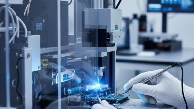
Why Choose the Right Laser Lens for Your Machine?
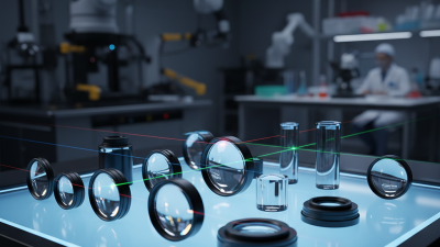
A laser machine can be well built and still produce uneven results when its lens does not suit the job. The right Laser Lens helps focus energy where it is needed, supporting clean cuts, consistent engraving, and more predictable processing. But “right” depends on the machine, the laser source, and the material. There is no single lens that performs best in every setup. Small details matter.
Focal length affects working distance, spot size, and depth of focus. A shorter focal length may create a fine spot for detailed engraving, while a longer one can provide more clearance for thicker materials. Wavelength compatibility and lens coatings also matter; a lens intended for one laser type may absorb or transmit energy differently with another. Check the machine manufacturer’s specifications before comparing products. A lower price alone tells you little.
A practical choice starts with the actual task: cutting plywood, marking coated metal, or engraving acrylic can place different demands on focus and heat control. Confirm the lens diameter, mount, rated power, and compatible wavelength, then compare those details with reliable product documentation. Keep the lens clean and inspect it for haze, scratches, or residue, since contamination can affect beam quality and may contribute to overheating. It is easy to blame the lens for every poor result. Sometimes alignment, settings, or material variation is the real cause. Testing carefully may take longer, but it can reveal whether the lens is truly the limiting part.
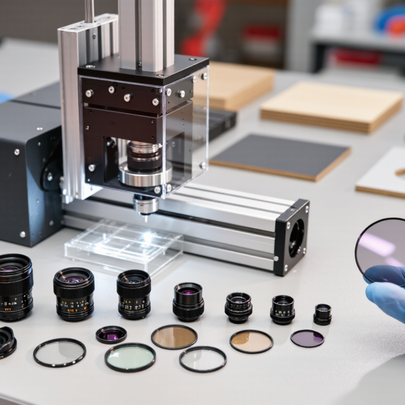
How Laser Lenses Focus Energy: Spot Size Depends on Beam Diameter and Focal Length
A laser lens does not create energy; it concentrates the beam into a smaller area. For a near-Gaussian beam, the approximate focused spot diameter is d ≈ 4M²λf/(πD), where λ is wavelength, f is focal length, D is the incoming beam diameter, and M² describes beam quality. In a calculated example, a 1,064 nm beam with a 6 mm diameter and M² of 1 forms an ideal spot near 22.6 µm with a 100 mm lens. Halving the focal length roughly halves that spot, assuming the beam still fills the lens correctly. The math is clean.
ISO 11146-1:2021 specifies methods for measuring beam widths, divergence, and propagation ratios, including M². Those measurements matter: a beam with M² above 1 will generally focus less tightly than the ideal example. A larger beam entering the lens can produce a smaller spot, but clipping at the lens aperture wastes energy and may distort the result. Reality intervenes. Lens aberrations, alignment, and the actual beam profile also change the spot on the work surface. I would treat the calculation as a starting point, then check the beam and cut quality at the machine’s working distance. A neat specification can still disappoint on the shop floor.
Why Choose the Right Laser Lens for Your Machine? — How Laser Lenses Focus Energy: Spot Size Depends on Beam Diameter and Focal Length
Illustrative spot-size comparison for different focal lengths using the same laser beam and optical conditions.
| Focal Length |
Estimated Focused Spot Diameter |
Relative Spot Area |
Relative Peak Irradiance |
General Trade-Off |
| 50 mm |
Approximately 13.5 µm |
1× |
1× |
Smaller estimated spot; typically a shorter working distance and a tighter focus-position tolerance. |
| 100 mm |
Approximately 27.1 µm |
4× |
0.25× |
Medium focal length that balances spot size, working distance, and coverage for many setups. |
| 150 mm |
Approximately 40.6 µm |
9× |
0.11× |
Larger estimated spot and longer working distance; useful when more clearance or a wider processing area is needed. |
Calculation basis: Ideal Gaussian-beam estimate using d ≈ 4M²λf/(πD), where d is focused spot diameter, M² = 1.2, λ = 1.064 µm, and D = 6 mm is the 1/e² beam diameter at the lens. Relative area and peak irradiance assume the same beam power; area scales with d² and peak irradiance scales approximately with 1/d². Actual results vary with beam quality, lens aberrations, aperture clipping, alignment, and the measured beam profile.
Match Lens Material to Wavelength: ZnSe for 10.6 μm CO₂, Silica for 1,064 nm
A laser lens is not interchangeable glass. Its material must transmit the machine’s wavelength with minimal absorption. For a 10.6 μm CO₂ laser, zinc selenide (ZnSe) is commonly used because it transmits this infrared wavelength well. The choice matters: excess absorption can heat the optic, distort the beam, and shorten lens life. Small details matter.
For a 1,064 nm laser, such as many near-infrared fiber systems, fused silica is often a suitable lens material. It offers strong transmission at this wavelength and can handle demanding beam conditions when correctly specified. Still, “silica” alone does not guarantee compatibility. Check the lens coating, rated power, and intended wavelength; a coating designed for one wavelength may perform poorly at another.
It is easy to focus only on focal length. That is not enough. A lens that fits the machine may still be wrong for its source, and damage can begin as a faint haze or a small change in cut quality. Confirm the laser’s actual wavelength and operating conditions against the optic’s specifications before installation. Even familiar setups deserve a second look.
Choose Focal Length: Common CO₂ Laser Lenses Range from 1.5 to 7.5 Inches
CO₂ laser lenses commonly range from 1.5 to 7.5 inches in focal length. The right choice depends on material thickness, desired detail, and working clearance—not laser power alone. A 1.5-inch lens can produce a small spot for fine engraving or thin sheet. But its short working distance leaves little room for uneven material. A 4- or 5-inch lens gives more clearance and can suit thicker stock. Longer is not always better.
Focal length also affects focus geometry. ISO 11146-1:2021 describes methods for measuring laser beam widths and propagation. Using Gaussian-beam optics, with beam quality and input beam diameter held constant, spot diameter scales approximately with focal length. An ideal 4-inch setup could therefore produce a spot about 2.7 times wider than a 1.5-inch setup. Its Rayleigh range would be roughly 7.1 times greater. These are calculated comparisons, not guaranteed machine results; alignment, beam quality, and lens condition can change performance. That distinction is easy to overlook.
Tips: Match the lens to your material’s thickness, then test on a scrap piece. Check focus at the surface and through the cut. Record the focal length and settings. A quick test often beats a confident guess.
CO₂ Laser Lens Focal Length and Theoretical Spot Size
Common CO₂ laser lens focal lengths range from 1.5 to 7.5 inches. The chart shows the ideal focused spot diameter calculated for a 10.6 μm laser beam with a 6 mm input beam diameter and ideal beam quality (M² = 1).
Longer focal lengths produce a larger theoretical spot under these assumptions. Actual results depend on beam diameter, beam quality, alignment, and lens condition; choose a focal length based on your material, desired detail, and working clearance.
Check Coatings and Transmission: Laser AR Coatings Often Exceed 99% at Design Wavelength
Why Choose the Right Laser Lens for Your Machine?
Check Coatings and Transmission: Laser AR Coatings Often Exceed 99% at Design Wavelength
A lens can look clear and still waste laser power through reflection. At normal incidence, an uncoated fused-silica surface reflects about 3.5% of incoming light, based on the Fresnel equation. A well-designed antireflection coating can raise transmission above 99% at its specified design wavelength. That figure is not universal: wavelength, angle, polarization, and temperature all matter. Check the transmission curve, not just the headline number.
For a practical comparison, match the coating specification to your laser’s actual wavelength and operating angle. A lens rated above 99% at one wavelength may transmit less when your setup shifts off that point. The ISO 21254 series describes test methods for laser-induced damage thresholds, a useful reference when checking whether an optic can withstand the machine’s power density. High transmission alone is not enough. A damaged coating can scatter light or reduce beam quality.
Tips: Ask for a measured transmission curve and damage-threshold data for your operating conditions. Inspect for haze or pinpoint defects under suitable lighting. Small imperfections matter. It is easy to focus on transmission and overlook alignment, but a slightly tilted lens can still spoil the beam.
Inspect and Clean the Lens: Contamination Can Reduce Transmission and Damage Optics
A lens can look clean at a glance and still carry a thin film of smoke, dust, or fingerprints. Inspect it under a bright, angled light before each maintenance session. Small specks matter. They can absorb energy, heat up, and create marks in a coating that may not be repairable. Even light contamination can reduce transmission and affect cut quality or focus consistency.
Switch off the machine and let the optics cool before inspection. Follow the machine’s service instructions; lens materials and coatings do not all tolerate the same cleaners. Use a clean air blower for loose particles, then a suitable optical tissue or swab if residue remains. Never rub dry debris across the surface.
A faint streak may be less harmful than a scratched coating, though it is frustrating to leave behind. Replace damaged optics rather than trying to polish them. Record recurring contamination, too: it may point to airflow or extraction problems, not just a lens-care issue. Cleaning helps, but it cannot correct every source of poor performance.