Leave Your Message

What Are the Top Shaft Repair Methods in 2026?

Shaft Repair in 2026 is less about choosing the newest process and more about matching the repair to the failure. A worn bearing seat, a bent shaft, and a cracked journal do not call for the same remedy. In paraphrase, machinery-reliability author Heinz P. Bloch’s guidance points to a core principle: correct the cause of failure, not only its visible damage. That distinction matters.

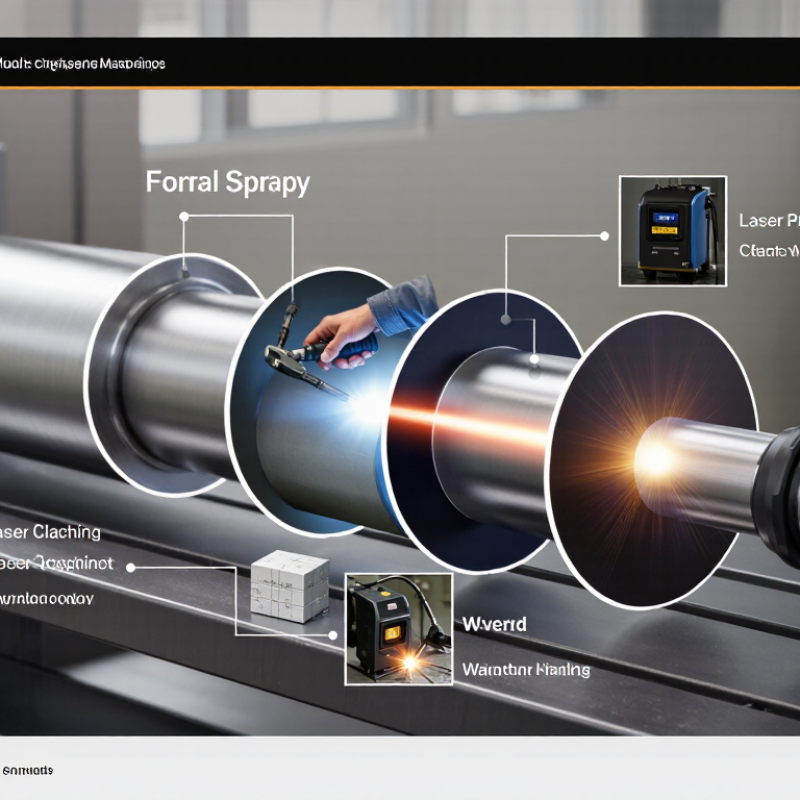
This guide compares common methods, including precision machining, thermal spray, laser cladding, weld overlay, and fitted sleeves. Each has limits. Machining may restore a clean bearing fit, but it can reduce shaft diameter. Thermal spray can rebuild a surface without substantial heat input, yet coating adhesion and final grinding demand control. Welding may suit some damage, though heat can distort a shaft or alter its metallurgy. Laser cladding offers precise deposition, but access, cost, and material compatibility can rule it out. No method is perfect.

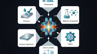
A sound decision starts with inspection: measure runout, check journal dimensions, identify material, and look for cracks. Then assess operating load, speed, lubrication, and the original failure mechanism. A shiny repair is not proof of a reliable one. Sometimes the repair itself becomes the next failure point. The sections ahead explain where each method fits, what evidence to request from a repair provider, and when replacement is the more dependable option. In 2026, documentation matters too: recorded measurements, process details, and post-repair checks make results easier to evaluate—not guaranteed.
What Are the Top Shaft Repair Methods in 2026?

Inspect Shaft Runout, Cracks, and Journal Wear Against OEM Limits

Before repair, measure shaft runout at the specified support points, with the shaft clean and correctly supported. Record total indicated runout at several journal locations, then compare each result with the OEM drawing or service limit. A dial indicator can reveal a bent section, but setup error can imitate one. Small numbers matter. Repeat the measurement after repositioning the shaft; one reading is not enough. Inspect crack-prone shoulders, keyways, and fillets using an appropriate nondestructive method. ASTM E165/E165M covers liquid penetrant testing for surface-breaking discontinuities; it does not detect every subsurface flaw.

Journal wear needs equally careful comparison. Measure diameter at multiple axial and circumferential points, and note taper, ovality, scoring, and heat discoloration. A micrometer reading alone may miss localized damage. If a crack is suspected, stop and establish its extent before machining or welding; the repair route depends on material, geometry, and OEM acceptance criteria. The U.S. Department of Energy’s 2010 Operations & Maintenance Best Practices Guide reports predictive-maintenance savings of 8–12% over preventive maintenance and 30–40% over reactive maintenance. Those figures are not shaft-specific, but they support planned inspection over failure-driven repair. I would not treat them as a guarantee. Keep the measurement record, instrument identification, and inspection method with the repair decision.

Restore Worn Journals with Thermal-Spray Coatings

What Are the Top Shaft Repair Methods in 2026?
Restore Worn Journals with Thermal-Spray Coatings

A worn journal can turn a smooth bearing seat into a ridged, undersized surface. Thermal spraying restores the diameter by depositing metal or alloy onto a prepared shaft, then machining it to the required fit. The ASM Handbook, Volume 5A: Thermal Spray Technology, describes coating thickness and properties as process- and material-dependent; wear-repair builds are often planned in the sub-millimeter range. The exact allowance must include finishing stock, not just the missing shaft material. A radial build of 0.25 mm increases the finished diameter by 0.50 mm.

Preparation matters as much as the coating. Technicians typically remove oil and damaged material, roughen the journal, apply the coating, and grind it concentric with adjacent seats. Inspection should check diameter, runout, surface finish, and coating adhesion. ISO 14923 outlines evaluation methods for thermal-sprayed coatings, while ASTM C633 measures their adhesion or cohesion strength. These checks help expose weak bonding before the shaft returns to service. Still, spraying is not a cure-all: deep cracks, severe distortion, or poor access may make another repair method more suitable.

Tips: Record the original journal diameter and runout before machining. Specify the final fit and finish in advance. Leave enough coating allowance for grinding, and verify adhesion on a representative test piece when the application is critical. A tight tolerance can be missed by a small margin.

Top Shaft Repair Methods in 2026: Typical Restoration Thickness

Indicative thickness ranges for common shaft restoration processes. Thermal-spray coatings can restore worn journals without the high heat input associated with welding; the suitable method and final thickness depend on the shaft material, wear, and service requirements.

Ranges are approximate and vary by process, application, and repair specification. Confirm dimensions and suitability with the repair procedure.

Rebuild Damaged Shafts Using API Standard 687 Repair Guidance

What Are the Top Shaft Repair Methods in 2026?
Rebuild Damaged Shafts Using API Standard 687 Repair Guidance

A shaft with scoring, fretting, or a bent journal needs a documented assessment before repair. API Standard 687 offers repair guidance for special-purpose rotating equipment. Use it to define inspection, repair scope, and acceptance checks—not as a substitute for the equipment’s design requirements. Start with cleaning and dimensional checks, then identify the material and inspect critical areas using suitable nondestructive testing. Small cracks matter. A repair that restores diameter but misses a crack is not a reliable rebuild.

Depending on damage and material, options can include machining and sleeving, thermal spray coating, or qualified weld restoration followed by machining. The repair plan should specify process controls, heat treatment when required, final dimensions, runout, and balance criteria. Keep inspection records and compare results with approved drawings and tolerances. The U.S. Department of Energy’s Operations & Maintenance Best Practices guide reports predictive-maintenance savings of 8–12% over preventive maintenance and 30–40% over reactive maintenance. These are broad maintenance estimates, not shaft-repair guarantees, but they reinforce the value of early condition checks. Repair decisions can be messy; replacement may be safer when damage or material history is uncertain.

Tips: Record journal diameters at several positions, photograph defects before machining, and verify balance after repair. Confirm acceptance limits with the equipment owner and applicable API 687 guidance. Don’t assume a smooth surface proves sound material.

Use Sleeves or Replace Shafts When Damage Exceeds Repair Limits

A shaft sleeve can restore a worn bearing seat when damage is localized and the shaft remains straight, crack-free, and structurally sound. The repair typically involves machining the journal, fitting a precision sleeve, then checking diameter, runout, and bearing fit. A sleeve is not a cure for everything. Cracks, deep corrosion, severe bending, or an undersized core can make replacement the safer choice. Follow the equipment drawing and applicable fit requirements; there is no single repair limit for every shaft.

Measure before deciding. Record journal diameter at several points, shaft runout, and the depth of any scoring. Magnetic-particle or dye-penetrant inspection can help reveal surface cracks, while ultrasonic testing may detect internal flaws. If machining to clean metal would leave the shaft below its specified minimum diameter, stop and assess replacement. A sleeve can conceal damage if inspection is skipped. That is an easy mistake.

The U.S. Department of Energy’s Operations & Maintenance Best Practices guide reports potential predictive-maintenance benefits of 25–30% lower maintenance costs and 35–45% less downtime. These figures describe program-level outcomes, not guaranteed savings from a shaft repair. Still, they support a practical habit: measure, inspect, and document before choosing a repair. Record the final dimensions and vibration readings, too. Imperfect records can make the next decision harder.

Verify Rotor Balance to ISO 21940-11 Grade G 2.5 Where Specified

Shaft repairs in 2026 may include journal grinding, metal build-up, or installing a fitted sleeve. Each method changes the rotor’s mass distribution. A smooth journal is not proof of a balanced rotor. Even a small amount of uneven material can cause vibration at operating speed. Check runout and dimensions after machining, then verify balance when the equipment specification requires it.

For specified applications, verify rotor balance to ISO 21940-11, Grade G 2.5. Confirm the rotor’s classification, service speed, and correction planes before testing; the grade alone does not define the full procedure. Use calibrated equipment and record the measured residual unbalance for each plane. If correction is needed, remove or add material only at approved locations, then repeat the measurement. Keep the balance report with repair records. A repair can meet dimensional limits yet still produce vibration, so investigate mounting, coupling, and bearing conditions when readings remain high.

Tips: Clean the rotor before testing. Confirm the specified grade with the equipment documentation. Small details matter. Don’t assume a factory balance requirement applies unchanged after every repair; verify the actual service specification.

What Are the Top Shaft Repair Methods in 2026? — Verify Rotor Balance to ISO 21940-11 Grade G 2.5 Where Specified
Repair method Typical application Key process considerations Main advantages Limitations and checks Balance and verification
Precision machining to an undersize Minor wear, scoring, or damage on a journal when the bearing or mating component can accept a smaller finished diameter. Establish the shaft’s runout and remaining dimensions, then machine and finish the journal to an agreed fit and surface finish. Simple repair with no added heat or deposited material; the finished surface can be inspected directly. Reduces shaft diameter and may affect fits, strength, seals, and fatigue life. Confirm dimensions and fits against the equipment requirements. Check runout and concentricity after machining. Balance the assembled rotor if required by the equipment specification.
Fitted sleeve or journal sleeve Worn bearing, seal, or coupling seats where a sleeve can restore the required finished diameter. Machine the damaged area, design the sleeve and its retention for the application, then finish-machine the sleeve concentrically with the shaft. Restores a usable running surface while avoiding a large-area heat process. Requires adequate shaft material and a sound retention design. Added interfaces and geometry must not compromise fit, stress capacity, or operating clearances. Measure journal runout and sleeve concentricity. Recheck balance after repair or assembly where specified.
Thermal spray coating Wear or corrosion restoration on suitable journals and cylindrical surfaces, subject to coating and service requirements. Prepare the substrate, apply a compatible coating, and machine or grind it to the required final dimensions and finish. Can restore dimensions with comparatively low heat input to the shaft relative to fusion welding. Coating adhesion, porosity, thickness, and service environment matter. It is not a substitute for repairing a cracked or structurally unsound shaft. Inspect the finished surface and shaft runout. Check balance after material removal or deposition when required.
Laser cladding Localized restoration of worn areas where a compatible cladding material and qualified repair procedure are available. Apply a metallurgically bonded layer using a controlled process, then machine or grind the area to final size. Can restore material locally and produce a metallurgical bond; the heat-affected area is generally more localized than with conventional weld build-up. Requires suitable material compatibility, process control, and post-process inspection. Heat input and distortion still need to be managed. Check dimensions, runout, and the repaired region using inspection appropriate to the material and procedure. Verify rotor balance where specified.
Weld build-up and finish machining More substantial localized material loss where the shaft material, geometry, and service conditions permit a qualified welding repair. Use an approved welding and heat-treatment procedure where required; control distortion, then machine and finish the repaired area. Can restore material where a thin coating or sleeve is unsuitable. Heat can cause distortion, residual stress, metallurgical changes, or cracking. Assess the shaft material and fatigue-critical areas before choosing this method. Use suitable post-repair inspection and dimensional checks. Rebalance the rotor if required by the machine specification.
Electroplated dimensional restoration Limited dimensional restoration or surface-property recovery on compatible shaft materials and applications. Select a compatible deposit and process, prepare the surface, and finish-machine or grind to the specified dimensions. Can restore a close-tolerance surface without the same bulk heat input as fusion welding. Deposit suitability, adhesion, thickness, fatigue conditions, and applicable environmental and regulatory requirements must be assessed. Not suitable for every shaft or damage type. Verify finished dimensions, surface condition, and runout. Balance verification depends on rotor requirements and the amount and location of material added or removed.
Replacement shaft or rotor Cracked, severely distorted, materially compromised, or uneconomical-to-repair shafts; also used when a repair cannot meet the required design limits. Confirm material, dimensions, fits, and rotor configuration against the approved design and equipment requirements. Avoids retaining damage that cannot be reliably repaired and inspected. Requires component availability, correct installation, and checks of connected components and alignment. Verify the completed rotor’s balance to the specified requirement, including ISO 21940-11 Grade G 2.5 when explicitly applicable.
Selection and balance note: The suitable repair depends on shaft material, damage extent, geometry, speed, loading, and the equipment manufacturer’s or engineering specification. Inspect for cracks and other relevant defects using methods appropriate to the material and service. ISO 21940-11 applies to rotors with rigid behaviour within its scope; Grade G 2.5 is not a universal requirement for every repaired shaft. Confirm the applicable balance grade, rotor condition, and operating speed before acceptance.